
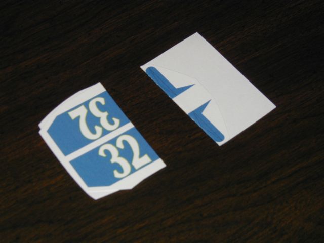
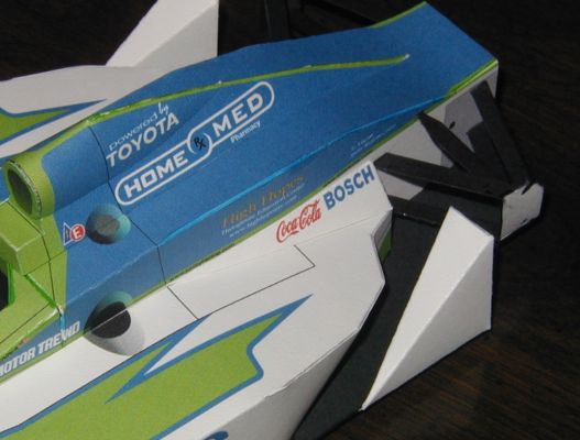
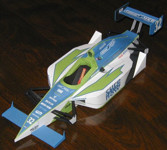
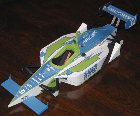
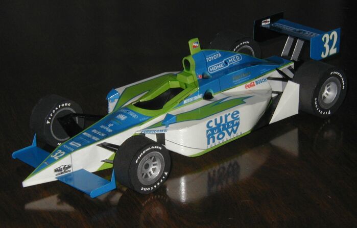
Photos show the Tony Renna #32 car, but all IR-03 cars are assembled in the same way.
Before getting into the instructions, a word about score lines is in order. Because I absolutely hate having score lines show up on a model, I use a few different types in order to minimize their appearance on the finished product. All tabs are scored along the bottom, along the edge of the colored area if there is no line apparent. Where there are two short dotted lines on each side of a part, connect the short lines with a score. If there is one long dotted line with an arrowhead, the score extends from the arrow across the adjacent surface and ends at the next corner. When all else fails and there must be a score line on the part, it will be a fine, slightly contrasting color line (or a dotted white line on black parts - easily touched up).
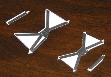
To save time later, start off by doubling up the wing endplates and suspension parts. When cutting out the main suspension piece, follow the part edge and dotted lines exactly on the inside and outside ends of the A-arms. Follow the lines on the tab ends of the pushrods and pullrods as well. Everywhere else can be cut out roughly. Spread a thin, even layer of glue on the parts (or use a glue stick), fold double, and weight down on a flat surface to dry overnight.
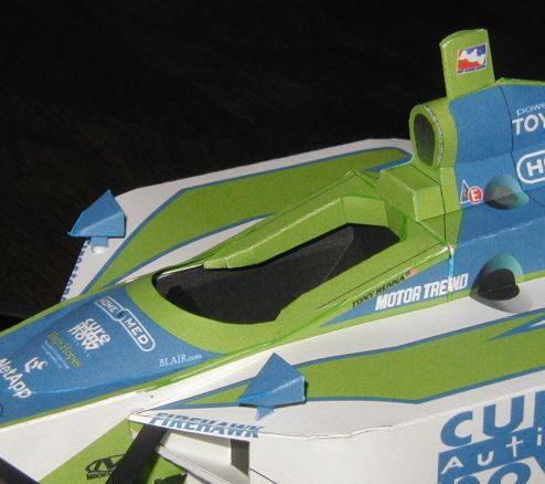
Score, cut out, and assemble the cockpit.
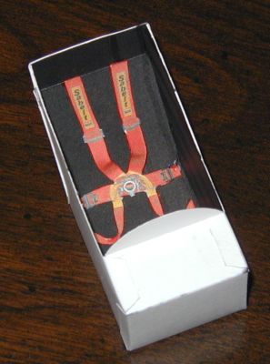
Carefully cut out the seatbelts. Fit and glue the belts in the location shown. Note that they do not lay flat, giving them a more realistic 3D appearance.
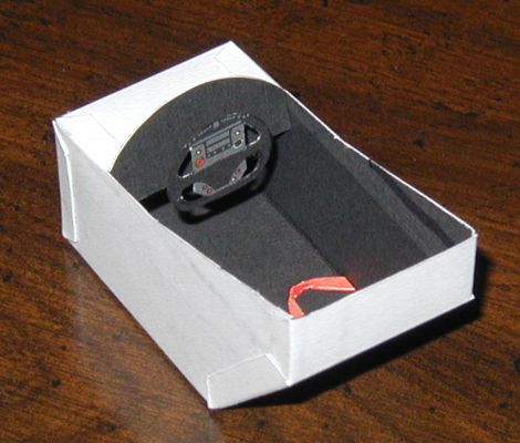
Score and cut out the steering shaft. The longer portion of the shaft is glued double, and the tabs are folded out, making a "T" shaped part. The top of the T is glued to the back center of the steering wheel. Place a small blob of glue on the end of the steering shaft, and assemble it to the dash in the white rectangle. When dry, assemble the dash assembly to the matching part of the cockpit, but do not glue the dash to the sides of the cockpit. This is so it can tilt back for the next step.
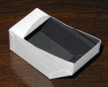
Start the front chassis assembly by scoring all the appropriate lines. Then cut out the cockpit opening, the ten small rectangles for the front suspension mounting, and the two small holes for the front wing spar (though the holes are shown as circles, they can be cut out as squares - the front wing covers the openings). Cut out the front chassis. Score and cut out the rear headrest as well. Fold down all the tabs in the cockpit opening 90 degrees and glue the edges of the front 3 tabs together. Now glue the rear headrest to the remaining tabs and the edges to the forward tabs.
Double-check to make sure all the small openings are cut out as described above. Now fold and glue the sides, top, and bottom together, leaving the rear open. Install the cockpit by tilting the dash back and sliding the assembly into the front chassis (see above photo). If the dash is too wide at the front of the opening, trim the sides of the dash back a bit - do not enlarge the opening. When satisfied with the fit, pull the cockpit back a bit, put a dab of glue on the top rear edge and in front of the dash, and push it back into place. Make sure the dash is vertical, and fold and glue closed the rear bulkhead. Be sure it is flush with the sides.
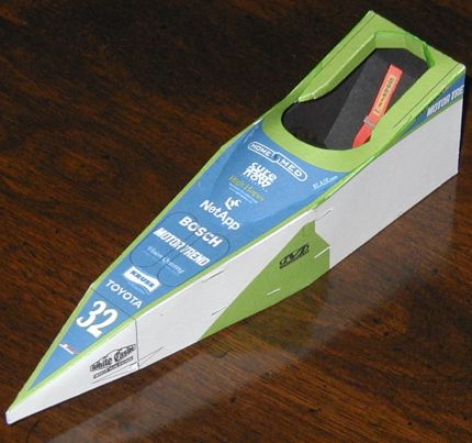
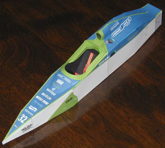
Cut out the windshield hump, and roll it to shape. Glue it into place, using markings to align it. You should now have something that looks like this:
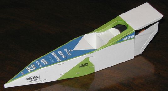
Score all lines on the rear chassis and cut out the 10 suspension mounting slots. Cut out the part, fold, and glue, again making sure the bulkheads are flush with the sides. Glue the rear chassis to the front chassis, as shown:
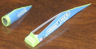
Score, cut out, and assemble the airscoop base. Score and cut out the airscoop top, and form it around a pen or small rod before gluing the back part together. Glue the airscoop front to it - there are small marks on the top of both pieces for alignment. Do not yet glue the top to the base.
Glue the airscoop base to the chassis assembly. The front should be flush with the back of the headrest, and the point at the rear should be centered side-to-side. Assemble the top of the airscoop to the base, making sure the bottom edges are rolled in enough to touch the sides of the airscoop base.
NOTE: If using a silver Sharpie finish on the suspension and a clear finish coat on the car, you may wish to delay this step until after clear-coating the rest of the car. However, dry-fit the front suspension to help locate the sidepods in the next step.
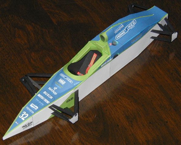
Trim the doubled suspension assemblies to their final shape. Using a pin, punch a small hole through the middle of the small circle on each upright (this is to help align the wheels later). Install each suspension assembly as shown. Note that on the rear assemblies, the cut-off corner of the upright is toward the top rear. Install the pushrods and pullrods, making sure each side is level with the other. When viewed directly from the front or rear, the rear suspension arms should be horizontal, and the front arms should angle up toward the wheels by about 1/8"(3mm).
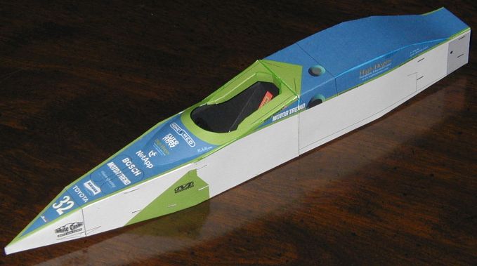
Score and cut out the sidepods. Note that the front opening on the right sidepod can be made either small or large. The small opening is normal for cars in superspeedway trim, as this model is.
Fold over the undertray doubler (pointy part at rear) and glue down, aligning the outside edges. Pre-bend the rear of the side skin along the scores, as shown in the two pictures below. Glue the top and side skins together. Starting at the front, glue the side skin to the bottom. To attach the rear portion of the side skin, run a line of glue along the inner edge of the undertray doubler with a toothpick. Gently push the side skin out against the edge of the doubler so there are no gaps. If you were sparing with the glue, it should dry in a minute or two.
Fold the inner skin and bulkheads up into place. Set the sidepod on a flat surface to check that the bottom surface is not twisted. Put a light pencil mark on the top and inner skins to assure alignment, and glue the inner skin into place. Fold up and glue the wheel flip to complete the assembly. Repeat the assembly for the other sidepod.
Assemble the sidepods to the chassis, using the light guidelines on the chassis to locate them. You may have to trim or bend the upper lip of the sidepod opening in order to clear the front suspension arm.
Score, cut out, fold, and assemble the sidepod fillets to the car.
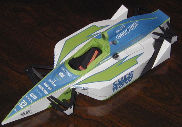
Assemble the front and rear wings as shown.
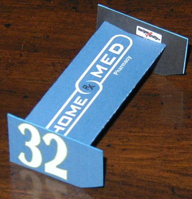
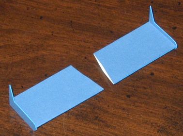
Score and cut out the rear wing mount/attenuator. Fold the wing mounts double and glue. Fold and glue the rest of the assemble together, then attach it to the bottom of the rear wing as shown.
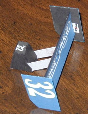
Glue the attenuator/rear wing assembly over the white area on the rear of the chassis. Slide a round toothpick through the small holes in the nose and center it. Apply glue to the inside edges of the front wings, then slide them over the toothpicks and align with the marks on the nose.
Assemble the camera pod and rearview mirrors to the car as shown. If you are putting a clear coat finish on your model, do so now.
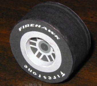
All wheels are assembled in the same way, but be sure to keep the parts for the front and rear wheels separate as they are slightly different sizes. Start by scoring the tabs on the tire tread and punching a pinhole through the center of each inner tire face. Cut out all the parts, then roll the tire tread and rim strip into a round shape and glue the ends together with the joining strips provided. Bend down the tabs on the tread, then glue the inner tire face to the tread. Glue the rim strip to the rim face, then glue the assembly to the outer tire face, as shown.
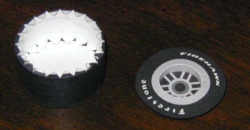
Glue the tire halves together. Align so that the seams on the tread and rim strip are 180 degrees apart, i.e. if you are looking straight at the tread seam, you can also see the rim strip seam in line with it. This is so that the wheels can be assembled to the car with all seams pointing down, to minimize visibility in the finished product.
If you haven't yet done so, glue the suspension parts to the car as described above. Assemble the wheels to the car, using a pin through the previously punched holes in the uprights and wheels to align them. Also cut short lengths of round toothpick to fit between the black dots on the sides of the transaxle and the white dots on the rear suspension uprights. Color them black before gluing into place.
Created on December 29, 2003